
Private: Chapter Seventeen
Galvanic Cells (17.2)
OpenStax
Learning Objectives
By the end of this section, you will be able to:
- Describe the function of a galvanic cell and its components
- Use cell notation to symbolize the composition and construction of galvanic cells
As demonstration of spontaneous chemical change, Figure 17.2 shows the result of immersing a coiled wire of copper into an aqueous solution of silver nitrate. A gradual but visually impressive change spontaneously occurs as the initially colorless solution becomes increasingly blue, and the initially smooth copper wire becomes covered with a porous gray solid.
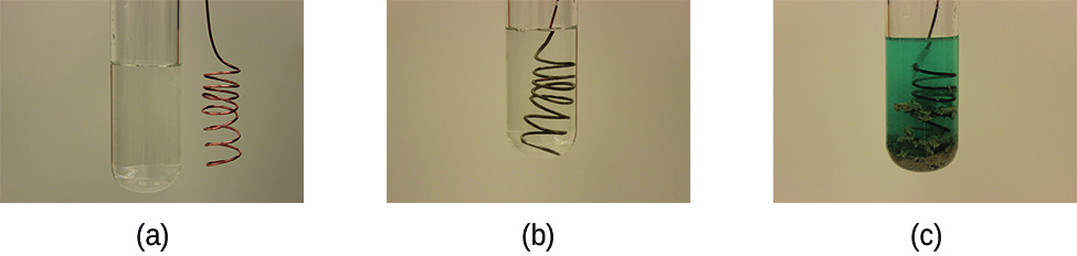
Figure 17.2 A copper wire and an aqueous solution of silver nitrate (left) are brought into contact (center) and a spontaneous transfer of electrons occurs, creating blue Cu2+(aq) and gray Ag(s) (right).
These observations are consistent with (i) the oxidation of elemental copper to yield copper(II) ions, Cu2+(aq), which impart a blue color to the solution, and (ii) the reduction of silver(I) ions to yield elemental silver, which deposits as a fluffy solid on the copper wire surface. And so, the direct transfer of electrons from the copper wire to the aqueous silver ions is spontaneous under the employed conditions. A summary of this redox system is provided by these equations:
overall reaction:Cu(s) + 2Ag+(aq) ⟶ Cu2+(aq) + 2Ag(s)
oxidation half-reaction:Cu(s) ⟶ Cu2+(aq) + 2e−
reduction half-reaction:2Ag+(aq) + 2e− ⟶ 2Ag(s)
Consider the construction of a device that contains all the reactants and products of a redox system like the one here, but prevents physical contact between the reactants. Direct transfer of electrons is, therefore, prevented; transfer, instead, takes place indirectly through an external circuit that contacts the separated reactants. Devices of this sort are generally referred to as electrochemical cells, and those in which a spontaneous redox reaction takes place are called galvanic cells (or voltaic cells).
A galvanic cell based on the spontaneous reaction between copper and silver(I) is depicted in Figure 17.3. The cell is comprised of two half-cells, each containing the redox conjugate pair (“couple”) of a single reactant. The half- cell shown at the left contains the Cu(0)/Cu(II) couple in the form of a solid copper foil and an aqueous solution of copper nitrate. The right half-cell contains the Ag(I)/Ag(0) couple as solid silver foil and an aqueous silver nitrate solution. An external circuit is connected to each half-cell at its solid foil, meaning the Cu and Ag foil each function as an electrode. By definition, the anode of an electrochemical cell is the electrode at which oxidation occurs (in this case, the Cu foil) and the cathode is the electrode where reduction occurs (the Ag foil). The redox reactions in a galvanic cell occur only at the interface between each half-cell’s reaction mixture and its electrode. To keep the reactants separate while maintaining charge-balance, the two half-cell solutions are connected by a tube filled with inert electrolyte solution called a salt bridge. The spontaneous reaction in this cell produces Cu2+ cations in the anode half-cell and consumes Ag+ ions in the cathode half-cell, resulting in a compensatory flow of inert ions from the salt bridge that maintains charge balance. Increasing concentrations of Cu2+ in the anode half-cell are balanced by an influx of NO−3 from the salt bridge, while a flow of Na+ into the cathode half-cell compensates for the decreasing Ag+ concentration.
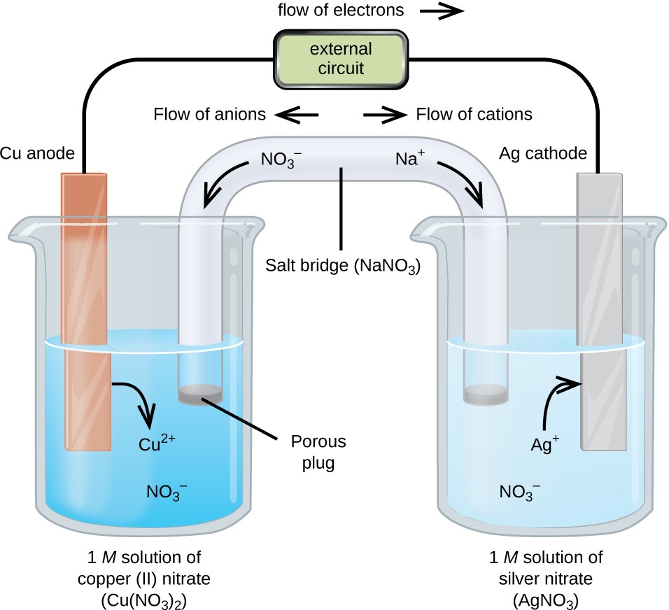
Figure 17.3 A galvanic cell based on the spontaneous reaction between copper and silver(I) ions.
Cell Notation
Abbreviated symbolism is commonly used to represent a galvanic cell by providing essential information on its composition and structure. These symbolic representations are called cell notations or cell schematics, and they are written following a few guidelines:
- The relevant components of each half-cell are represented by their chemical formulas or element symbols
- All interfaces between component phases are represented by vertical parallel lines; if two or more components are present in the same phase, their formulas are separated by commas
- By convention, the schematic begins with the anode and proceeds left-to-right identifying phases and interfaces encountered within the cell, ending with the cathode
A verbal description of the cell as viewed from anode-to-cathode is often a useful first-step in writing its schematic. For example, the galvanic cell shown in Figure 17.3 consists of a solid copper anode immersed in an aqueous solution of copper(II) nitrate that is connected via a salt bridge to an aqueous silver(I) nitrate solution, immersed in which is a solid silver cathode. Converting this statement to symbolism following the above guidelines results in the cell schematic:
Cu(s) │ 1 M Cu(NO3)2(aq) ║ 1 M AgNO3(aq) │ Ag(s)
Consider a different galvanic cell (see Figure 17.4) based on the spontaneous reaction between solid magnesium and aqueous iron(III) ions:
net cell reaction:Mg(s) + 2Fe3+(aq) ⟶ Mg2+(aq) + 2Fe2+(aq)
oxidation half-reaction:Mg(s) ⟶ Mg2+(aq) + 2e−
reduction half-reaction:2Fe3+(aq) + 2e− ⟶ 2Fe2+(aq)
In this cell, a solid magnesium anode is immersed in an aqueous solution of magnesium chloride that is connected via a salt bridge to an aqueous solution containing a mixture of iron(III) chloride and iron(II) chloride, immersed in which is a platinum cathode. The cell schematic is then written as
Mg(s) │ 0.1 M MgCl2(aq) ║ 0.2 M FeCl3(aq), 0.3 M FeCl2(aq) │ Pt(s)
Notice the cathode half-cell is different from the others considered thus far in that its electrode is comprised of a substance (Pt) that is neither a reactant nor a product of the cell reaction. This is required when neither member of the half-cell’s redox couple can reasonably function as an electrode, which must be electrically conductive and in a phase separate from the half-cell solution. In this case, both members of the redox couple are solute species, and so Pt is used as an inert electrode that can simply provide or accept electrons to redox species in solution. Electrodes constructed from a member of the redox couple, such as the Mg anode in this cell, are called active electrodes.
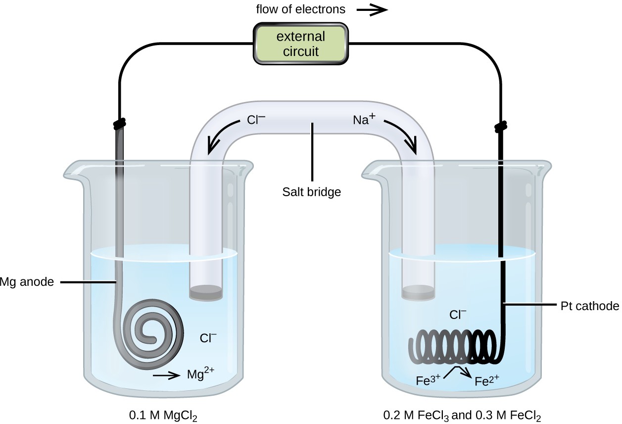
Figure 17.4 A galvanic cell based on the spontaneous reaction between magnesium and iron(III) ions.
Example 17.3
Writing Galvanic Cell Schematics
A galvanic cell is fabricated by connecting two half-cells with a salt bridge, one in which a chromium wire is immersed in a 1 M CrCl3 solution and another in which a copper wire is immersed in 1 M CuCl2. Assuming the chromium wire functions as an anode, write the schematic for this cell along with equations for the anode half-reaction, the cathode half-reaction, and the overall cell reaction.
Solution
Since the chromium wire is stipulated to be the anode, the schematic begins with it and proceeds left-to- right, symbolizing the other cell components until ending with the copper wire cathode:
Cr(s) │ 1 M CrCl3(aq) ║ 1 M CuCl2(aq) │ Cu(s)
The half-reactions for this cell are
anode (oxidation):Cr(s) ⟶ Cr3+(aq) + 3e−
cathode (oxidation):Cu2+(aq) + 2e− ⟶ Cu(s)
Multiplying to make the number of electrons lost by Cr and gained by Cu2+ equal yields
anode (oxidation): 2Cr(s) ⟶ 2Cr3+(aq) + 6e−
cathode (reducation): 3Cu2+(aq) + 6e− ⟶ 3Cu(s)
Adding the half-reaction equations and simplifying yields an equation for the cell reaction:
2Cr(s) + 3Cu2+(aq) ⟶ 2Cr3+(aq) + 3Cu(s)
Check Your Learning
Omitting solute concentrations and spectator ion identities, write the schematic for a galvanic cell whose net cell reaction is shown below.
Sn4+(aq) + Zn(s) ⟶ Sn2+(aq) + Zn2+(aq)
Answer: Zn(s) │ Zn2+(aq) ║ Sn4+(aq), Sn2+(aq) │ Pt(s)
