
4.11 Powering the Ship
“This team of engineers ensures that the ship is supplied with power, air conditioning, waste management and fresh water day and night, and on a ship like the JOIDES Resolution, power is everything!” — Katie Halder, IODP EXP 363, Who is the Most Important Person on the Ship? How far could we get without engineers?
The Team
- Chief Engineer
- 1st Assistant Engineer
- 2nd Assistant Engineer
- 3rd Assistant Engineer
- Senior Motorman
- Motorman
- Oiler
- Welders (four on board)
“The vessel was almost 50 years old, and with age comes degradation of steel as she works in seawater – thus, corrosion will take place. Our team has to maintain the safe structural integrity of the vessel as well as working with the Deck crew to slow down the corrosion process by properly treating and painting the steel structures of the vessel, inside and out. This is an ongoing and never ending process, and if done correctly, the result contributes to the longevity of the vessel. Most vessels built today are only built to last approximately 10 years unlike those built back in the 70’s.”
– Chief Engineer Jack O’Connor, 3 Dec 2024
On any given day of an expedition, crew members would be seen bustling across the decks, tools in hand as they diligently completed their tasks and checks. For the crew, a dull moment simply meant it was time to move on to the next item on the priority list of preventative or maintenance work. With so many systems to manage, the marine engineers truly became “jacks of all trades,” excelling at a wide variety of tasks.
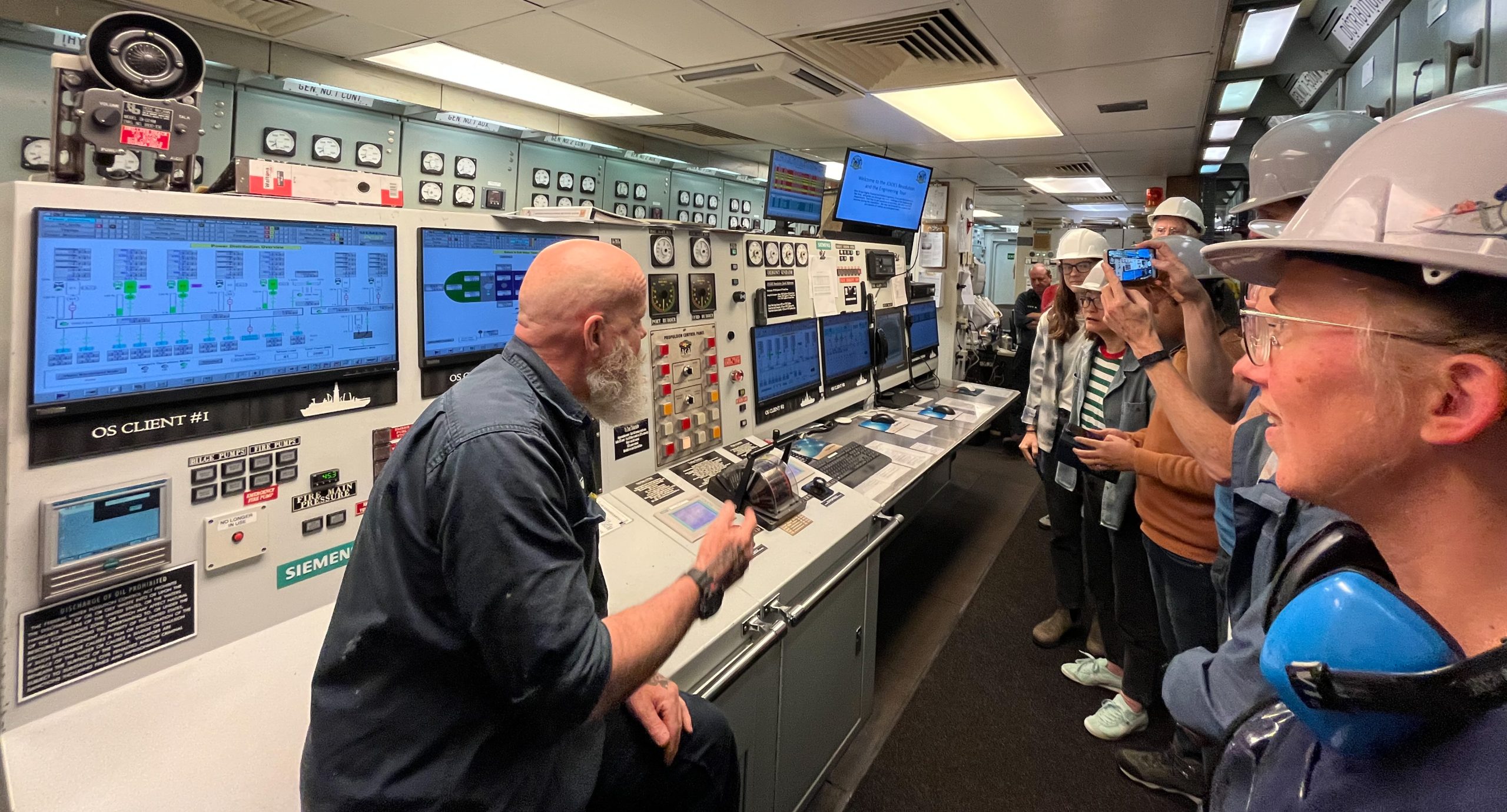
Engine Control Room (ECR)
In the Engine Control Room, a cluster of monitors on the main desk, circuit breakers on the walls, and other electrical equipment were observed by watchkeeping engineers. But the engineers were not alone in their surveillance duties—there was also the Data Management System (DMS), an automated software application that digitally checked all interconnected systems. The DMS both monitored and calculated when extra power was needed and seamlessly started or stopped engines to match the ever-changing demands of the power plant.
The marine engineers, as stated above, always found something to do, but that task wasn’t always in the ECR. The watchkeeping task would alternate so that everyone could take breaks and offer their expertise somewhere else on the ship if needed. Nevertheless, the watchkeeping duties required there were always two people in the ECR. These engineers could react much faster to any alarms or issues than the computer system because of two reasons: (1) there were built-in time delays in the computer system; and (2) the engineers were more up-to-date on current situations and happenings on the ship, which allowed them to make more informed decisions if alarms went off. Nevertheless, the DMS was a necessary back up.
Operations monitored by the DMS and engineers were:
- Sea water cooling
- Compressed air
- Potable water (transfer and service)
- Drill water (transfer and service)
- Fuel oil (transfer and service)
- Water makers
- Ventilation
- AC chillers and air handlers
- Provision refrigeration and container system
- Sewage collection and treatment system
- Grey water collection and discharge systems
- Bilge and ballast systems
- Fire fighting systems
- Steering gear system
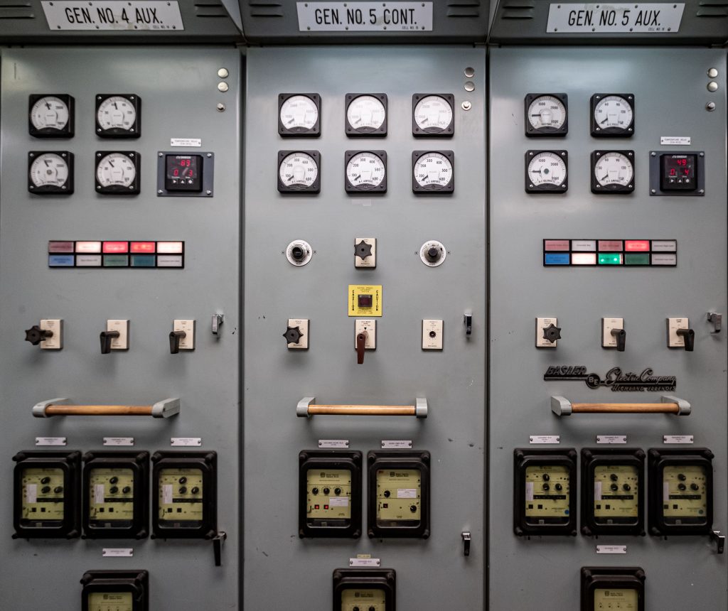
As one looked away from the monitors at the main desk, the walls of the Engine Control Room (ECR) were lined with a multitude of circuit breakers. Each breaker was responsible for distributing electrical power to its designated system throughout the ship. One set of panels housed 4160-volt circuit breakers, which managed electricity for systems such as Thyrigs C through H, the Tie Transformer (which converted power between 4160 and 480 volts), 4160-volt generators 1 through 5, and the Forward Load Center. Another set of panels contained 480-volt circuit breakers, which supplied power to 480-volt generators 6 and 7, various 480-volt pieces of equipment, Motor Control Centers, and shore power. While most of these operations were automated through the Data Management System (DMS), they could be manually operated if needed, though the process was far more complex.
Steering the ship in an emergency from the ECR
A point many engineers highlighted during ship tours is that they could “drive the ship” from the Engine Control Room (ECR) if needed. On regular days at sea, the ship is steered and operated by the sailing crew from the Bridge. However, in the event of a dire emergency—such as encountering pirates—the engineers had a backup method to take control of the ship.
Using a control panel in the steering compartment, they can switch circuit breakers to override the Bridge’s control of the ship’s steering. In this scenario, engineers in the ECR would manage the throttles and adjust the RPMs (rotations per minute) of the propulsion shafts, while personnel in the steering compartment would manually steer the ship. The main drawback is that neither the ECR nor the steering compartment has windows to see the surroundings. However, both rely on a compass for navigation. A communication system between the steering compartment and the ECR ensures coordination between the engineers and the sailing crew, enabling them to navigate based on compass directions and safely guide the ship to address the emergency.
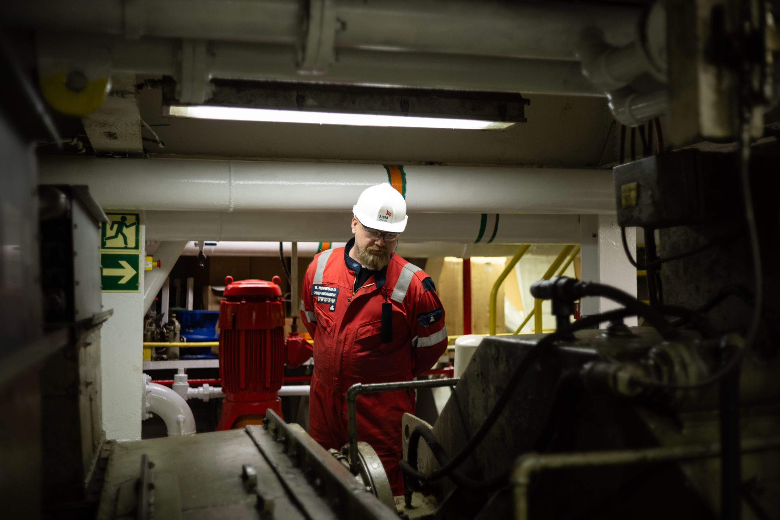
Engine Room
JOIDES Resolution had seven diesel engines that created a lot of heat as fuel was burned. During expeditions in cold climates, the engine room warmed up to fairly warm temperatures. But when expeditions sailed in hotter climates, the engineers had to take frequent breaks outside the engine room to avoid becoming overheated. As much as the temperature in the engine room could swing between tolerable and unbearable, having multiple engines provided the engineers the ability to service the engines on a rotating schedule without having to reduce power to the ship.
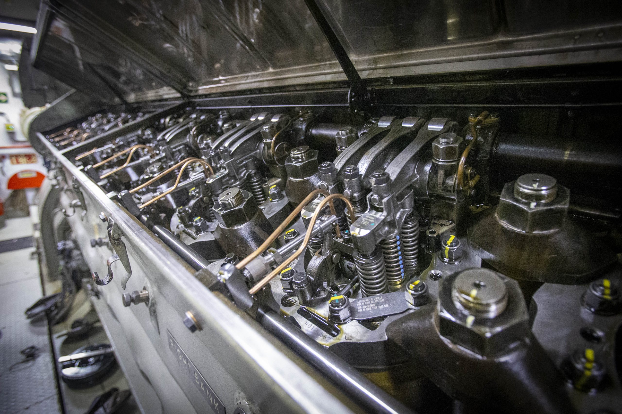
The engines of the JR were built around 1975 and had been on the ship ever since installation. Although all the engines were installed at the same time, they comprised two different models: five 16-645-E9 engines and two 16-645-E8 engines. The difference between the models was marked by the cylinder displacement and how they generated stationary power.
Stationary power referred to the energy produced that was not directly used for propulsion systems. The E9 engines generated stationary power with turbochargers that used exhaust gas turbines to run a compressor, which varied the amount of air entering the engines. This design allowed the E9 engines to produce more horsepower, but only when they were running at 75% capacity or higher. The E8 engines, on the other hand, generated stationary power using roots blowers, which had compressors that controlled specific amounts of air flowing in and out of each cylinder to maintain steady horsepower. To ensure consistent power generation, all engines were synced with generators to turn at a speed of 900 RPMs, enabling the production of electricity for the ship.
Even with the two engine types, all of them worked together to produce electricity that powered 12 electric motors. These motors rotated the shafts of two massive propellers, each 4 meters in diameter. The engines also provided the energy to power essential onboard systems mentioned earlier. Together, the propulsion system produced an output of 9,000 horsepower.
How To Get Fuel to The Engine
The vessel JOIDES Resolution required a lot of fuel to last two months at sea. There were multiple storage tanks throughout the ship, and fuel from any one of those tanks was pumped to the settling tank in the Engine room through a strainer and two sets of filters. Every six hours, as the fuel settled, a small amount was drained to check for any dirt and water.
From the settling tank, the fuel was moved through a heater and a fuel oil purifier. The purifier was used to separate any water or dirt from the fuel, if any, by acting as a centrifuge. Once through, the fuel sat in the day tank. As the engines needed to be refueled, the fuel was pulled from the day tank through another two sets of strainers before the fuel was injected into each cylinder of that engine. The multilevel set of filters, and purifiers before the fuel ever reached the engines, were put in place to ensure the reliability and integrity of the engine systems.
Tour the Engine Room
Go on a engine room tour with the Entier staff in the video below. The video was adapted from the full length YouTube video by LezVentures (a staff member of the Entier crew). It was shortened to feature just the tour of the engine room. Be aware that audio in the film makes it hard to hear what they are saying in the engine room and at the end of the tour.
The Engine Room was an extremely loud room, possibly the loudest on the whole ship. For anyone to work or even visit, they were required to wear ear protection like ear plugs or over the head protection. There were many compartments to the engine room, and during a tour one was able to see the five engines, and the accompanying fuel tanks and fuel oil purifiers, plus some other spaces:
Ship Service Generator Room
- Two engines/ generators
- Emergency air compressor
- Cold start air compressor
- Access to Skeg Thrusters (11 and 12)
- Engineer workshop
The Motor Room
- The two shafts that housed the propulsion motors and gearboxes
- The two cooling systems that consisted of a blower that pumped air through the motor, and a circulating water system that cooled the air that left the motor to maintain the ambient air temperature in the room manageable
- Oil pumps for the gear boxes
- Ballast water treatment system
- Fuel transfer pumps
- Oily water separator that would filter and process waste water (function is to only release waste water with less than 5 parts per million of oil contaminant)
- Fire pump and foam pump
Aft Machinery Room
- Two water makers
- Engineer workshop
Thyrig Room
The Thyrig Room’s main job was to convert AC (alternating current) voltage into DC (direct current) voltage and adjust the voltage levels to match the needs of different equipment. For example, some panels reduced 4160 AC volts down to 850 DC volts to power the ship’s drilling equipment, propulsion systems, and thrusters. This was because DC motors operated between 0 and 850 volts, which made it easier to control their speed compared to the larger, less precise AC motors.
The ship had several Thyrig bays, each responsible for powering specific systems. For example,
- Thyrig Bays A and B, located under the gym, powered Thrusters 1 through 6. Such thrusters were used during drilling operations and the ship had to stay above the drilling site.
- Thyrig Bays G and H supplied power to the drilling equipment, including systems like the drawworks, top drive, core winch, mud pumps, and cement pumps.
- Thyrig Bays C, D, E, and F powered the ship’s propulsion motors. Each bay had its own sub-bay, with each sub-bay dedicated to a single motor during transit. When the ship was moving between locations, all power was sent to the propulsion motors. But when the ship reached a drilling site, it switched to a station-keeping mode. In this mode, the Dynamic Positioning (DP) system divided the power, sending half to the thrusters to maintain the ship’s position and the other half to the propulsion motors.
