4.6 Adjusting the Ship for Horizontal and Vertical Motion
To respond to wind and water conditions during the drilling process, ships rely on their technology to keep in position horizontally and to adjust for vertical fluctuations caused by the sea. It is the dynamic position system and heave compensator that allow for drilling safety and better chances for a higher percentage of core recovery.
Before exploring some of the equipment on board scientific ocean drilling vessels that allow for safe ocean navigation and core recovery, review this short video to learn about the motions ships experience while at sea.
Exercise: Demonstrating the Six Types of Ship Motion
Towards the end of the video Beyond the Wow: The Six Types of Ship Motion, viewers are encouraged to grab a nearby object and demonstrate each of the motions described. See how you do carrying out the following:
a) Pitch b) Roll c) Yaw d) Heave e) Sway f) Surge
If you would like to see a written description of each motion, visit the Ocean Exploration Trust blog post.
As we move forward with learning about shipboard instrumentation to accommodate for these motions, keep in mind that although the descriptions on this page focus specifically on JOIDES Resolution. The drilling vessels CUSS 1 and Glomar Challenger also had similar systems in place to address the movement of the ship at sea. Here, we explore the dynamic positioning system (addressing surge, sway, and yaw,) and the heave compensator (guarding the drilling process against heave).
Dynamic Positioning System
When JOIDES Resolution was located in deep water, it was not possible to utilize an anchor to maintain a static position. So when the JR was in water that was over a mile deep with a drill string winding its way down to the ocean floor and beyond, how did she stay in one place? With her Dynamic Positioning System.


The JR’s Dynamic Positioning (DP) System used data from two different types of position systems in order to stay over a drill hole. The primary positioning system was the Global Positioning System (GPS). There were three GPS systems on board that worked to calculate the position of the ship. Each GPS system acted independently to triangulate the position and then the DP System averaged those out to come up with the ship’s actual position. An older method that wa still used as a backup to GPS was an acoustic beacon. The beacon was dropped overboard and settled to the ocean floor where the ship needed to remain. It would send out a signal that the ship’s hydrophones received and these signals were used by the DP System. This was once the primary positioning system onboard, but as GPS became more accurate and reliable, the beacons remained as an effective and reliable backup system.
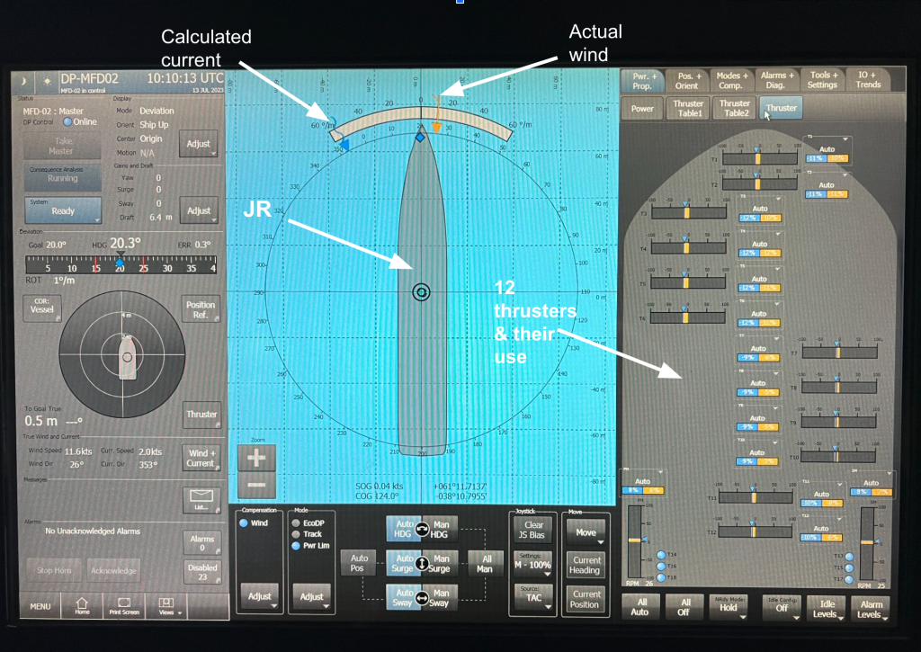
The DP system used position data and other information to make a computer model of the ship in the water, and used the desired location as a “home base”. The Captain would set the direction of the bow (heading) based on wind direction, energy requirements, and the needs of the expedition. Then, the computer would use this information to send power to the required thrusters (the JR had 12 thrusters) and to the two main propellers to maintain this heading and position. The heading would be chosen for fuel efficiency, but it could also be one that was more comfortable for everyone on board (time to think about sea-sickness), or advantageous to conducting drilling operations (think “heave” or up and down motion of the vessel and drill assembly).

But it is not that simple. There were other factors that the computer was required to take into account when keeping the ship steady. The wind direction and speed affected how much energy the system would send to each of the thrusters for compensation. The wind was constantly being measured by anemometers on the ship. This information was sent directly to the computer for immediate adjustments for any wind changes. Water currents and other forces were more difficult to measure on the ship, so the computer calculated a current estimate and used that as data.

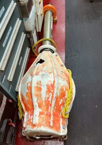
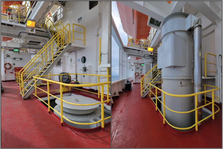
Above are photos of the actual thrusters and ship propellers from when JOIDES Resolution was in Amsterdam Dry Dock (IODP EXP 384P) in 2020. Hover over individual images for descriptive text to appear. (Photos provided by Jennifer Hertzberg, IODP/JRSO DAM Administrator)
When the JR was drilling, the DP System operated similar to an auto-pilot, but unlike a land-based vehicle, the JR was in constant and sometimes severe motion. As waves made the ship pitch and roll, moving the GPS antennas (and hydrophones), the DP System may have registered that the ship was actually changing position. However, this type of motion would be adjusted for by the DP computer, using Motion Reference Units (MRU) attached to the ship. There was also a fail-safe, or “dead reckoning” mode which would turn on if the ship lost all GPS input. It would work to maintain its current position as long as it could, even without the external data. This gave the Captain time to figure out what was going wrong, and to fix the problem.
This was one of the many systems that facilitated drilling activities on JOIDES Resolution. And while most of the attention was being paid to the drilling and the core material retrieved from the deep sea, all of these computations would be taking place in a room on the bridge. It is this system that made it possible for the JR to send miles of drill pipe into the ocean floor and pull up Earth’s past, present, and future in the form of core.
Heave Compensator
Heave is the up and down movement of a ship. Heave compensators are designed to counteract vertical movements due to waves. But when it comes to a scientific drilling vessel, the heave compensator ensures that the drill string remains stable relative to the seabed, so the compensation is for the pipe, not for the ship.
As this short video shows, the ship may appear stationary, but is actually moving. As the ship moves up and down, the heave compensator comes in to play.
In the following video, JR Operations Supervisor Bill Rhinehart explains how the heave compensator works to allow the JR to keep drilling, even when seas are not the smoothest.
Note that when he says, there is “20 foot of stroke on the compensator” he is referring to the maximum distance the compensator could move (or “stroke”) up and down to adjust for the heaving motion of the vessel or platform. In this case, the compensator could move up to 20 feet (~ 6 meters) vertically, which means it could absorb or counteract heave displacements of up to 20 feet. This kept equipment, such as drilling rigs or cranes, stable and prevented them from being affected by the vertical motion of the sea.
JR Operations Supervisor Bill Rhinehart explains how the heave compensator works (Credit: E. Anthony, IODP EXP 401).
Exercise: Data Exploration of Ship Heave
This video was recorded on JOIDES Resolution during IODP Expedition 390 on May 2, 2022. This is an example of what the South Atlantic Ocean was like at the JR’s position on this date.
Daily ship heave data from IODP Expedition 390 (South Atlantic Transect 1) has been pulled together and is presented in a Google Sheet. The Sheet can be downloaded and the data can be worked with to respond to the following questions:
a) If you were to plot this data for heave, what type of graph would you create? Which data would you put on each axis?
b) Which day had the highest average heave? Was it the same day that had the highest maximum heave? Why might these days be the same date or different dates?
c) Why might someone want to look at the maximum heave instead of the average heave?
d) What other data could you look at to better understand the heave experienced by the ship? For example, would it be helpful to know if there were strong winds that day? Would the heave matter if it was a sunny day? Etc.
e) What do you think it would be like to walk on a ship during a day with a large heave? Do you think you could sleep during a day with a heave of three feet? Six feet? Ten feet? Explain.
The content for the Dynamic Positioning section of this page was modified from Jennifer Field’s post on the JOIDES Resolution blog, Dynamic Positioning. The ship heave data and exercise was modified from Laura Guertin’s post on the JOIDES Resolution blog, Expedition 390 Ship Motion (Heave), As Told Through Data (backup copy of blog post available here).

