8 Assemblies Cost Estimating
Learning Objectives
After reading this chapter, you should be able to:
- Describe the benefits and limitations of the assemblies estimating approach
- Develop an assemblies estimate for a building project
- Calculate the approximate cost differentials for selecting various system options for a project
Introduction
Once a project design progresses to a level where systems are defined, the team can continue with estimates that leverage the system information. If we refer back to our design phases, this level of estimates is primarily aligned with design development, when the systems are being designed, although some systems may be designed prior to this phase. These systems could include items as simple as the number of lavatories or toilets. It could also be more complex such as an assemblies estimate per square foot of building area for a mechanical system, such as rooftop units. It is important to note that some of the quantities used to develop the assemblies are straightforward, such as the number of units for the lavatories, although others are more abstract, such as the square footage of the building for the mechanical system. An estimating team within a construction firm may have their own assemblies costs that they have historically tracked and categorized. This chapter will focus on using the Gordian guide for assemblies as a public source of cost information.
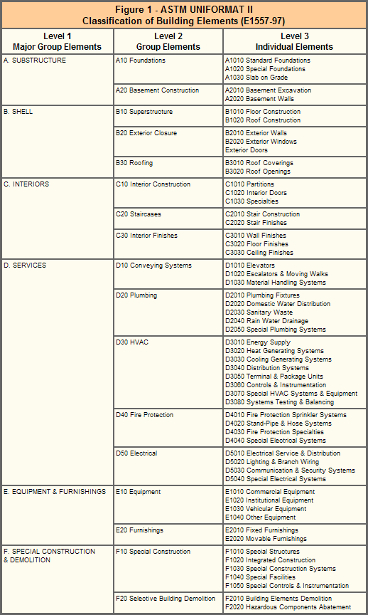
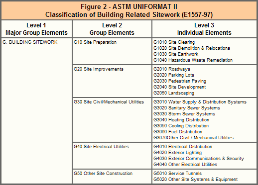
Assemblies estimates for commercial building projects are typically organized by CSI Uniformat 2 categories (see Figures 1 and 2) since they align with the overall building systems. This classification system is focused on building systems such as substructure (A), shell (B), interiors (C), services (D), equipment and furnishings (E), special construction and demolition (F), and building sitework (G) (see Figure 1 and 2 for the more detailed level 2 and 3 for each of these main – level 1 – categories). Uniformat II has four levels withing the hierarchical structure: Level 1: Major Group Elements (a letter); Level 2: Group Elements (2 digit number); Level 3: Individual Elements (2 digit number); and Level 4: Sub Elements (a three digit number). For more details on Uniformat II see this website with video from Gordian (link).
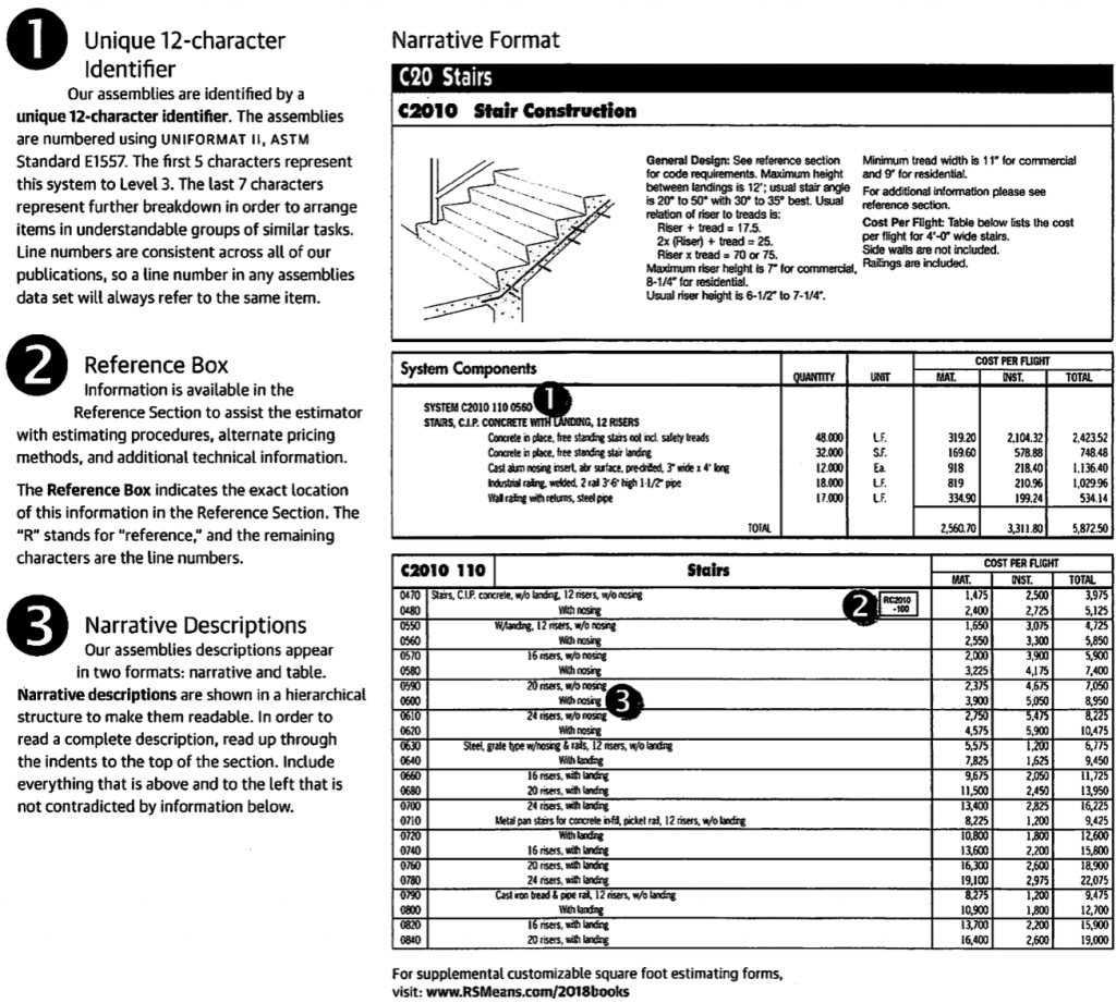
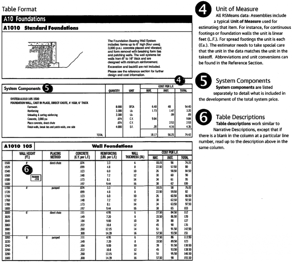
To develop a full assemblies estimate for a project, an initial takeoff of the quantities for each type of building system is needed, along with an understanding of the type of building systems. The Gordian Assemblies Estimating Guide contains directions regarding the information provided for each assembly. Figures 3 and 4 contain the descriptions for the different information that is published for each of the assembly categories within the Gordian Assemblies Guide with RS Means data.
Each assembly is defined within the Gordian guide with a unique identifier along with a clear description of the detailed items within the assembly. For example, the stair construction assembly (A1010) shown in Figure 4 is developed by combining six more detailed items for a cast-in-place (C.I.P.) foundation wall. These six items are shown in the System Components section (noted with the number 5 in the image). These detailed items include formwork, reinforcing, reinforcing material handling, concrete, and finishing. It is important to note that you can read more details about what is included, and what is not included, in the description. For example, in Figure 4, we can see that excavation and backfill are not included in the foundation wall assembly. This assembly will be estimated with the unit of ‘cost per linear foot’ of the wall (see number 4 in Figure 4). It is important to note that you can not see the details for every assembly, but instead, you only see the details for one typical assembly per page. This one example is highlighted with its unique 12-character identifier (see number 1 in Figure 3 for example and the reference in number 2 in the same figure). For the remaining assemblies, you may need to assume the specific detailed items included, or you may have access to this information if you use the online version of the cost guides.
Steps to Complete an Assemblies Estimate
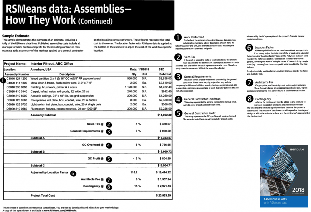
Figure 5 provides a summary of how to compile an assemblies estimate, including potential additions to the estimate, depending on the purpose. For example, this figure shows the compilation of the work performed at the top of the sample estimate (item 1 in the figure). This work performed will include each of the assemblies included in the scope of work. This simple example includes eight items related to interior fit-out, but for a full building, this may be several pages of assemblies outlining all of the systems for the substructure, superstructure, enclosure, MEP systems, and finishes (see the Uniformat II categories for complete list). After these systems are priced, using the R.S. Means data within the Gordian guide, then you would include additions such as sales tax, general requirements, overhead, and profit. Following these additions, you would revise the estimate based upon the location and time factors, as we do for all estimates using R.S. Means data. Finally, based on the audience and purpose of the estimate, you may add design/architect fees and contingency. A more detailed set of steps with additional notes follows.
Step 1: Identify the Assemblies within the Design
Review the design for the project and identify each assembly within the scope of work for the estimate. These assemblies will be organized by Uniformat II categories. Once you identify an assembly, it is valuable to identify the unit of measure for that assembly. This could be linear feet, square feet, number of units, or many other options. This unit of measure is important to complete the quantity takeoff.
Step 2: Perform Quantity Takeoff for Each Assembly
After identifying assemblies, you will perform a quantity takeoff for each assembly. This may include calculating distances or areas, or it may including counting number of items, e.g., lavatories. It may be helpful to use software for this takeoff process, such as BlueBeam.
Step 3: Identify the Cost per Unit for Each Assembly
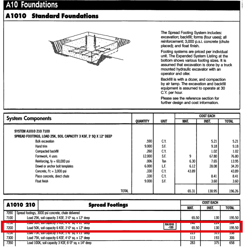
The R.S. Means data includes a cost per unit for many defined assemblies. For example, in the red box in Figure 6, the cost for a standard 3′ x 3′ x 12″ deep footing that supports 50,000 lbs on soil with a bearing capacity of 6,000 lbs/sf is $195.50 (per each footing). If you wish to see the detailed items included in calculating this unit price, you can read the description and look at the typical list of items included in the assembly cost. Note that the system components are only for one of the specific systems, e.g., in the case of Figure 6, the system component list for specifically for Assembly A1010 210 7100.
It is common that the exact assembly within the design may not be included in the Gordian guide. This may be for multiple reasons. One may be the size of the item varies, e.g., if you have a 3′ x 3.5′ x 12″ footing, there is not specific assembly for this size. In this case, you could estimate a value between two different assemblies with relatively close sizes. You may also have an assembly that does not have the exact system components within the assembly. In this case, you could look at the system components, and alter the assembly using more detailed unit cost items (which we will discuss in the next chapter) in order to create a new custom assembly cost. This requires integrating both the assembly and detailed estimating methods. If you are using computer software to compile the estimate, the software may be quite helpful in performing this process to develop custom assembly prices.
Step 4: Add all the Assembly Costs Together
After you have priced all assemblies, you’ll need to compile the final costs for each assembly by multiplying the units by the takeoff values, and then summing the values.
Step 5: Add Sales Tax
One new item for assemblies estimating is the addition of sales tax. Sales tax is calculated by the state in which the material is purchases, e.g., the sales tax in Pennsylvania is 6% on materials, while in Texas it is 6.25% and Deleware is 0%. Note that some locations have both state and city level sales taxes. In an assembly estimate, you can assume that approximately 50% of the cost of work performed is for materials and equipment, and therefore you would only apply sales tax to 50% of the value of the work performed.
Step 6: Add General Requirements, Overhead and Profit
Following the calculation of the direct cost of work (which includes the taxes on materials), then you will add the general requirements to cover the temporary facilities and general conditions costs on the project, e.g., management, etc. Then, you would add the overall company overhead and profit (see Figure 5 for the calculation approach).
Step 7: Modify for Time and Location
As with all estimates using R.S. Means data, you will need to modify the estimate based on the time and location of construction. Note that Figure 5 does not include the adjustment for time, but if it is not built at the time of the guide, there should be a time modification.
Step 8: Add any other Items
After you get the final cost of direct work with general requirements, overhead and profit, modified for time and location, you may wish to add other items to the estimate depending upon the audience. This could include design fees (if it is an estimate for both design and construction), or it may include contingencies for unknown costs.
Review Questions
References
Gordian. (2018). Assemblies Estimating Cost Guide.
Gordian. (2024). What is Uniformat II. Available at https://www.rsmeans.com/resources/uniformat-ii?srsltid=AfmBOoocF6WaUQCdz-YzqfVazPZ0SvRyOER6X5LPL-ZC_Mpomxt4kxOn

