
13 Designing a Site Utilization Plan
Learning Objectives
After reading this chapter, you should be able to:
- Define the items needed in a site utilization plan.
- Understand the core concepts for designing the site utilization plan for various stages of a project.
- Be able to define and draw a site utilization plan for a project.
Site Utilization Planning
A site utilization plan documents the designed status of a project at a point in time. Site Utilization Plans are critical to defining the layout of a project site as it progresses through the construction process. The site is continuously changing. Therefore, there is no one representation that represents the progression of the site throughout the construction process. But, instead, it is critical to have at least several site utilization plans to define the progress of the site, for example, a site utilization plan for the excavation phase, superstructure phase, enclosure phase, and finishes phase.
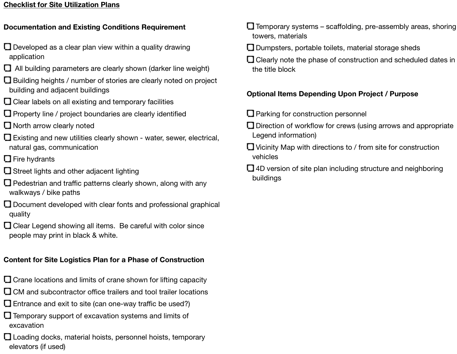
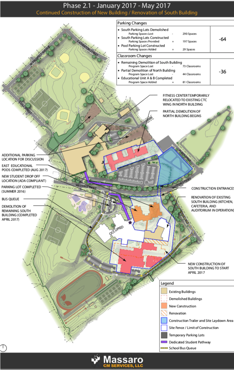
The checklist included in Figure 1 provides typical items that should be included in a Site Utilization Plan. Figure 2 shows a quality example of a site plan for a school project.
Developing a Site Layout Model
In addition to developing individual plans for the site utilization plans, it can be valuable to develop a 3D model of the site. This will enable you to gain a better understanding of the site characteristics and constrains at various phases of a project. There are many software tools than can be used to develop a 3D site utilization plan, including design authoring tools such as Revit, or geometric modeling tools such at SketchUp. Here is an interesting tutorial that shows some valuable approaches to developing a 3D site utilization plan leveraging SketchUp and a library of temporary site objects in the 3D Warehouse: construction-site-logistics-planning-with-sketchup
4D Modeling:
A site utilization plan can be incorporated with a Critical Path Method (CPM) schedule to develop a visualization model of the construction sequence for a project, known as a 4D model (3D geometry + time as the 4th dimension). These models can be fairly simple or very elaborate depending upon the level of detail of both the 3D model and the detail contained within the 3D model. Some simply show the final building elements, while others contain temporary equipment, site elements, formwork, etc. An example of a 4D model of the U.S. Bank Stadium construction can be found at this link.
Review Questions
